LDraw to SimCity 3000 Unlimited Tutorial
Warning! This article is a legacy article from the old site. It is provided for historical context and information may no longer be relavent.
This article was written for POV-Ray version 3.6 and L3P version 1.3, and has not been updated to reflect the newer software.
By: Michael Horvath (talk)
Introduction:
This tutorial instructs you on how to import LDraw models into SimCity 3000 Unlimited. You should already know how to build models using LDraw or MLCad and render them using POV-Ray. Maxis, the makers of SimCity 3000 Unlimited, have created their own tutorial on how to render objects and import them into the game. It is not required to complete this tutorial; but if you'd like to read it anyway, you can find it here.
Required Software
For starters, let's go over the programs involved: SimCity 3000 Urban Renewal Kit (SC3URK) is a program created by Maxis that allows you to design and import your own buildings into SimCity 3000 Unlimited. It is not included on the SimCity 3000 Unlimited installation disk. Instead, it is available as a separate download from the SimCity website (see the Links section below). You will also need a paint program, such as Windows Paint. You will also need a program called L3P to convert your LDraw model to POV-Ray format. You will need POV-Ray to render your 3D model into 2D images.
Links:
Instructions:
- Build a model in LDraw or MLCAD.
- Orient your completed model so that it is centered within the coordinate system, with the bottom of the model resting upon the x-z plane, as shown below:
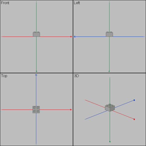
In the above image and for demonstration purposes, the x-axis is colored red, the y-axis is colored green, and the z-axis is colored blue. The coordinate axes will not appear when editing your own model. - Convert your model into a *.POV file using L3P.
- The lighting needs to be modified so that there are a total of six spotlights oriented according to the following scheme:
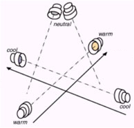
Open up the *.POV file in POV-Ray and replace the light sources with the following code:// Warm lights: light_source { <0, 0, 100000,> color rgb <255/255, 249/255, 232/255,> spotlight parallel point_at <0, 0, 0,> } light_source { <0, 0, -100000,> color rgb <255/255, 249/255, 232/255,> spotlight parallel point_at <0, 0, 0,> } // Neutral lights: light_source { <0, 0, 0,> color rgb <198/255, 198/255, 198/255,> * 0.75 spotlight parallel point_at vaxis_rotate(<0, 100, 0,>, x, 30) translate <0, -100000, 0,> } light_source { <0, 0, 0,> color rgb <198/255, 198/255, 198/255,> * 0.75 spotlight parallel point_at vaxis_rotate(<0, 100, 0,>, x, -30) translate <0, -100000, 0,> } // Cold lights: light_source { <100000, 0, 0,> color rgb <98/255, 98/255, 133/255,> * 1.3 spotlight parallel point_at <0, 0, 0,> } light_source { <-100000, 0, 0,> color rgb <98/255, 98/255, 133/255,> * 1.3 spotlight parallel point_at <0, 0, 0,> } - Now, replace the background and camera with the following code:
// Background color background {color rgb <1, 0, 1,>} // Default tile size; 1 = 1x1 tile; 2 = 2x2 tile, etc. #declare Tile = 4; // Camera rotation angle around the vertical axis #declare Rotate = 0; // Camera: camera { #local LegLength = sqrt(pow(640, 2) / 2) * 2; orthographic sky -y up y * LegLength * Tile * image_height / image_width right x * LegLength * Tile location vaxis_rotate(<1, 0, 1,>, <1, 0, -1,>, 30) * LegLength * Tile look_at <0, 0, 0,> rotate y * Rotate #if (frame_number > 0) rotate y * 360/final_frame * (frame_number - 1) #end } - Change the TILE keyword to reflect the width of your building, measured in SimCity tiles. To preserve the proper scale, one SimCity tile should equal one LDraw baseplate. You can rotate the camera around the y-axis by changing the ROTATE keyword to an angle in degrees. For instance, if the camera normally faces the NW corner of your model, you can change the ROTATE keyword to equal 180 to have it face the SE corner of your model.
- Create a new text file and paste the following code into it:
 ;; SC3URK 128px x 512px Output Bitmap
 Width = 128
 Height = 512
 Final_Frame = 4                 ;; Number of frames/views
 Final_Clock = 3                 ;; Number of frames/views minus one
 Output_File_Name = c:\lego\ldraw\images\
- Save or rename this text file as LDR2SC3K.INI and place it within the RENDERER directory in your POV-Ray installation directory.This file determines the height and width dimensions of the final images that POV-Ray will generate, as well as the number of images (frames) that will be rendered. A total of four images will be rendered -- one for each direction: NW, NE, SW and SE. The images should be 128 pixels wide if your building is 1x1 tiles in size, 256 pixels wide if it is 2x2 tiles in size -- and so forth, increasing in width by 128 pixels for each additional tile. You will need to experiment in order to determine what values are suitable for the HEIGHT parameter, as they will vary depending on your building's height.The last line specifies the directory you would like the rendered images saved to. Change this to a preferred location. Make sure you leave a back-slash ('\') at the end of the path.
- To render your model, select RENDER from the POV-Ray menu. Then, select EDIT SETTINGS/RENDER. Where it says INI FILE, click on BROWSE and find the LDR2SC3K.INI file. Once it's selected, click OK. Now click on SET BUT DON'T RENDER. This should bring you back to the main POV-Ray window. Now, click on the green RUN icon at the top of the screen. POV-Ray will now render your model and output the images into the directory you specified in LDR2SC3K.INI.
- If you are using BAT to import your images into SimCity 3000 (i.e., not SimCity 3000 Unlimited), you will have to crop the images in a paint program so that they properly fit the template images included with the program (you can also find them on the SimCity web site). If you are using SC3URK, instead (as is recommended), you will need to crop your images so that your building is aligned with the sides and bottom, like this:

- Run SC3URK and import the images. Make sure you import them in the correct order.
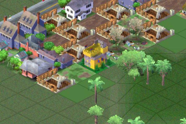
- After you've imported them into SimCity 3000 or SimCity 3000 Unlimited, an in-game screenshot featuring your completed building should look something like this:
- Follow steps 1 through 3 in the first tutorial.
- Download and decompress the archive. Place the *.INC file within the INCLUDE directory of your POV-Ray installation directory. Place the *.INI file within the RENDERER directory of your POV-Ray installation directory.
- Open up your *.POV file in POV-Ray and replace the background, camera, and light sources with the following declarations and include-statements: // Default tile size; 1 = 1x1 tile; 2 = 2x2 tile, etc. #declare Tile = 4; // Camera rotation angle around the vertical axis #declare Rotate = 0; // SC3URK Scene Description Language #include "LDR2SC3K.INC" Change the TILE declaration to reflect however wide your building is (in tiles):
- Select the *.INI file from the POV-Ray RENDER menu (see step 6, above). Render the images by pressing RENDER.
- Crop and import your building images into SimCity 3000, as described in steps 7 and 8, above.


That's it! You're done!
Alternative instructions:
As an alternative to the above steps, you can also install a set of *.INC and *.INI files that I have created for you and conveniently included in a ZIP archive. This is a shortcut and will allow you to achieve the same results.