T-Junction: Difference between revisions
No edit summary |
No edit summary |
||
| (4 intermediate revisions by the same user not shown) | |||
| Line 19: | Line 19: | ||
Notice the white dots. If you view the file in wireframe, you'll see that these dots occur along the seams between polygons. Please note that the actual coordinates of all the points in the file are fine (as far as I know; I haven't checked, but I believe Mike). The dots are there because from that point of view, the edges are diagonal, and diagonal edges require rounding. Essentially, the rounding cannot be guaranteed to be the same on the polygons along the edge if those polygons don't share common end-points on both ends. | Notice the white dots. If you view the file in wireframe, you'll see that these dots occur along the seams between polygons. Please note that the actual coordinates of all the points in the file are fine (as far as I know; I haven't checked, but I believe Mike). The dots are there because from that point of view, the edges are diagonal, and diagonal edges require rounding. Essentially, the rounding cannot be guaranteed to be the same on the polygons along the edge if those polygons don't share common end-points on both ends. | ||
This may be difficult to understand. Hopefully the following will illustrate the point: | This may be difficult to understand. Hopefully the following will illustrate the point: | ||
[[Image:T_Junction3.png]] [[Image:T_Junction3a.png]] | |||
These images were done in Microsoft Paint (then blown up by 800%), with two sets of lines that are designed to be right next to each other. The image on the left represents the T-Junction case. The one on the right represents the case without a T-junction. As you can see, there are gaps in the image on the left. This isn't quite the same as T-junctions in a part file, since the above sets of lines were drawn with 1 pixel difference. However, since 3D renderers are representing adjoining polygons with an infinitely thin edge between them, it actually works out to a very similar problem. (Note that the red line in the left image was actually drawn starting at the bottom-most green pixel, and the green line was then drawn with the same end-point.) | These images were done in Microsoft Paint (then blown up by 800%), with two sets of lines that are designed to be right next to each other. The image on the left represents the T-Junction case. The one on the right represents the case without a T-junction. As you can see, there are gaps in the image on the left. This isn't quite the same as T-junctions in a part file, since the above sets of lines were drawn with 1 pixel difference. However, since 3D renderers are representing adjoining polygons with an infinitely thin edge between them, it actually works out to a very similar problem. (Note that the red line in the left image was actually drawn starting at the bottom-most green pixel, and the green line was then drawn with the same end-point.) | ||
| Line 26: | Line 27: | ||
Additionally, T-Junctions prevent smooth shading algorithms (like the ones used in LDView) from working on curved geometry (like minifig faces). The reason that this is so is complicated, and not really important to understand. What is important to understand is that T-Junctions on '''any''' curved surface will prevent smoothing algorithms from working on that surface to visually removing the facets. In fact, they can cause very strange visual artifacts. | Additionally, T-Junctions prevent smooth shading algorithms (like the ones used in LDView) from working on curved geometry (like minifig faces). The reason that this is so is complicated, and not really important to understand. What is important to understand is that T-Junctions on '''any''' curved surface will prevent smoothing algorithms from working on that surface to visually removing the facets. In fact, they can cause very strange visual artifacts. | ||
==Getting | == Getting Rid of T-Junctions in Your LDraw Part == | ||
As far as I know, a T-junction in a triangle or quad can always be removed by the addition of one triangle. This can be tedious, but I don't know of any automated solution. Also, there are often better ways to get rid of T-junctions than adding a triangle. For example: | As far as I know, a T-junction in a triangle or quad can always be removed by the addition of one triangle. This can be tedious, but I don't know of any automated solution. Also, there are often better ways to get rid of T-junctions than adding a triangle. For example: | ||
| Line 32: | Line 33: | ||
[[Image:T_Junction4.png]] [[Image:T_Junction5.png]] [[Image:T_Junction6.png]] | [[Image:T_Junction4.png]] [[Image:T_Junction5.png]] [[Image:T_Junction6.png]] | ||
Notice that the rigtmost version is made up of 4 quads, while the middle version has 3 quads and 2 triangles. That makes the rightmost version better, sort of. Most renderers will at some point divide all the quads into triangles, and both versions result in the same number of final triangles, so it's not necessarily as much better as it might look. (I mention this, because things get a whole lot more complicated as the shapes become more complex, and it's really not worth trying to figure out the configuration with the fewest number of lines in the LDraw file. The differences are just too minor for that to be worth it.) | |||
Notice that the | |||
So the most basic way to get rid of a T-junction is to add a new triangle inside an existing quad or triangle. One thing that you DON'T want to do is convert a triangle into a quad in order to avoid a T-junction. This won't actually work right. | So the most basic way to get rid of a T-junction is to add a new triangle inside an existing quad or triangle. One thing that you DON'T want to do is convert a triangle into a quad in order to avoid a T-junction. This won't actually work right. | ||
In the example | [[Image:T_Junction7.png]] | ||
In the above example, the correct thing to do is split the triangle into two separate triangles: A•B•D and B•C•D. If you create a quad A•B•C•D, the tracker might reject the part (degenerate quad), but even if it doesn't, it's bad. As I said above, the renderer will likely split the quad into two triangles. The thing is, there's no way to know how that split will go. So it could choose A•B•D and B•C•D, or it could choose A•B•C and A•C•D, which ends up being a triangle with a T-junction and a degenerate triangle (line). LDView will actually pull the D point out of the quad at load time and treat it as a triangle (and spit out a warning). | |||
This all gets much more complicated when the T-junctions happen along the edges of primitives like disks. Sometimes it's not even possible to get rid of the T-junctions when using primitives, and at least with circular primitives, I think that it's better to use a circular primitive with a T-junction that can't be removed than it is to avoid the circular primitive in order to avoid the T-junction. | This all gets much more complicated when the T-junctions happen along the edges of primitives like disks. Sometimes it's not even possible to get rid of the T-junctions when using primitives, and at least with circular primitives, I think that it's better to use a circular primitive with a T-junction that can't be removed than it is to avoid the circular primitive in order to avoid the T-junction. | ||
[[Category: | [[Category:Terms]] | ||
Latest revision as of 21:49, 5 April 2018
T-Junctions in LDraw parts can often lead to unavoidable rendering artifacts, so it's best to avoid them when possible.
By Travis Cobbs.
Definition
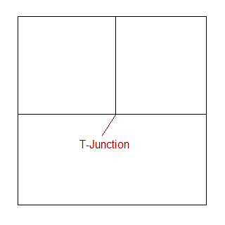
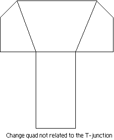
A T-junction is a spot where two polygons meet along the edge of another polygon, like so:
If these occur in a random location along a diagonal edge, it's often the case that the precise coordinates of the junction cannot be put into the DAT file. Many people would agree that that would be bad. However, when they occur at precise coordinates, it's tempting to say that there's nothing wrong with them, since there shouldn't be any round-off problems. Unfortunately, when you go to arbitrary 3D views, this turns out not to be the case.
It turns out that a 3D rendering engine can only guarantee that a closed polygon mesh is tight (no visible gaps) if the mesh does not contain any T-junctions. The reason for this is that once you start rotating things in 3D, the precise coordinates stop being precise.
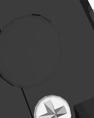
The following illustrates this problem:
Notice the white dots. If you view the file in wireframe, you'll see that these dots occur along the seams between polygons. Please note that the actual coordinates of all the points in the file are fine (as far as I know; I haven't checked, but I believe Mike). The dots are there because from that point of view, the edges are diagonal, and diagonal edges require rounding. Essentially, the rounding cannot be guaranteed to be the same on the polygons along the edge if those polygons don't share common end-points on both ends.
This may be difficult to understand. Hopefully the following will illustrate the point:
These images were done in Microsoft Paint (then blown up by 800%), with two sets of lines that are designed to be right next to each other. The image on the left represents the T-Junction case. The one on the right represents the case without a T-junction. As you can see, there are gaps in the image on the left. This isn't quite the same as T-junctions in a part file, since the above sets of lines were drawn with 1 pixel difference. However, since 3D renderers are representing adjoining polygons with an infinitely thin edge between them, it actually works out to a very similar problem. (Note that the red line in the left image was actually drawn starting at the bottom-most green pixel, and the green line was then drawn with the same end-point.)
Additionally, T-Junctions prevent smooth shading algorithms (like the ones used in LDView) from working on curved geometry (like minifig faces). The reason that this is so is complicated, and not really important to understand. What is important to understand is that T-Junctions on any curved surface will prevent smoothing algorithms from working on that surface to visually removing the facets. In fact, they can cause very strange visual artifacts.
Getting Rid of T-Junctions in Your LDraw Part
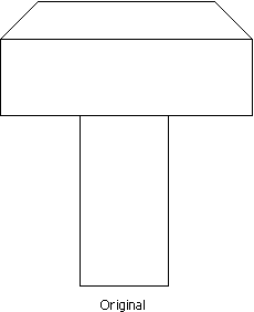
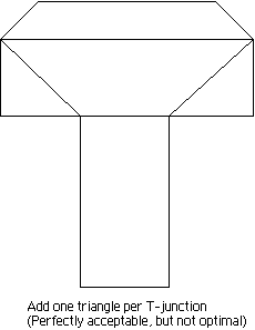
As far as I know, a T-junction in a triangle or quad can always be removed by the addition of one triangle. This can be tedious, but I don't know of any automated solution. Also, there are often better ways to get rid of T-junctions than adding a triangle. For example:
Notice that the rigtmost version is made up of 4 quads, while the middle version has 3 quads and 2 triangles. That makes the rightmost version better, sort of. Most renderers will at some point divide all the quads into triangles, and both versions result in the same number of final triangles, so it's not necessarily as much better as it might look. (I mention this, because things get a whole lot more complicated as the shapes become more complex, and it's really not worth trying to figure out the configuration with the fewest number of lines in the LDraw file. The differences are just too minor for that to be worth it.)
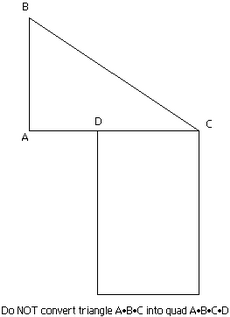
So the most basic way to get rid of a T-junction is to add a new triangle inside an existing quad or triangle. One thing that you DON'T want to do is convert a triangle into a quad in order to avoid a T-junction. This won't actually work right.
In the above example, the correct thing to do is split the triangle into two separate triangles: A•B•D and B•C•D. If you create a quad A•B•C•D, the tracker might reject the part (degenerate quad), but even if it doesn't, it's bad. As I said above, the renderer will likely split the quad into two triangles. The thing is, there's no way to know how that split will go. So it could choose A•B•D and B•C•D, or it could choose A•B•C and A•C•D, which ends up being a triangle with a T-junction and a degenerate triangle (line). LDView will actually pull the D point out of the quad at load time and treat it as a triangle (and spit out a warning).
This all gets much more complicated when the T-junctions happen along the edges of primitives like disks. Sometimes it's not even possible to get rid of the T-junctions when using primitives, and at least with circular primitives, I think that it's better to use a circular primitive with a T-junction that can't be removed than it is to avoid the circular primitive in order to avoid the T-junction.
