Stereoscopic 3D Glasses Tutorial: Difference between revisions
Created page with "==Introduction== Stereoscopic imaging works on the principle that each eye sees a slightly altered image, which are then combined in our mind to form a 3D mental picture. In p..." |
|||
| (26 intermediate revisions by the same user not shown) | |||
| Line 3: | Line 3: | ||
==Instructions== | ==Instructions== | ||
===Step 1: Using | ===Step 1: Using LDView=== | ||
The first thing you want to do is create your LDraw model in MLCad, LDCad, or whatever 3D modeler you prefer. When you are done, load your model in LDView and position your camera where you intend to view the scene from. In my case, I used the default camera orientation. When your camera is positioned properly, go to the "File > Export..." dialog, and export your model to a POV-Ray file. Again, I used the default settings, but you can change them to whatever you want to increase the render quality and so forth. | The first thing you want to do is create your LDraw model in MLCad, LDCad, or whatever 3D modeler you prefer. When you are done, load your model in LDView and position your camera where you intend to view the scene from. In my case, I used the default camera orientation. When your camera is positioned properly, go to the "File > Export..." dialog, and export your model to a POV-Ray file. Again, I used the default settings, but you can change them to whatever you want to increase the render quality and so forth. | ||
<gallery> | |||
File:Stereoscope 01.png | |||
File:Stereoscope 02.png | |||
</gallery> | |||
Note that L3P versions 1.3 and 1.4 both natively support stereoscopic views, so you may be able to skip some of the next few steps if you decide to go that route. | |||
===Step 2: Using POV-Ray=== | ===Step 2: Using POV-Ray=== | ||
[[File:Stereoscope 03.png|thumb|256px|right]] | |||
Once you've exported your model in LDView, you should open the file in POV-Ray. If you are using POV-Ray version 3.7 and LDView version 4.1, the first thing you will want to do is insert the following code at the top of the file. Otherwise, the colors will all be messed up. Future versions of LDView may not suffer cause this problem. | Once you've exported your model in LDView, you should open the file in POV-Ray. If you are using POV-Ray version 3.7 and LDView version 4.1, the first thing you will want to do is insert the following code at the top of the file. Otherwise, the colors will all be messed up. Future versions of LDView may not suffer cause this problem. | ||
| Line 26: | Line 33: | ||
look_at LDXCameraLookAt | look_at LDXCameraLookAt | ||
angle 57.822403 | angle 57.822403 | ||
translate -LDXCameraLookAt | |||
#switch (camera_eye) | #switch (camera_eye) | ||
#case (0) | #case (0) | ||
#include "transforms.inc" | #include "transforms.inc" | ||
Axis_Rotate_Trans(+y, +5/2) | |||
Axis_Rotate_Trans(y, +5/2) | |||
#break | #break | ||
#case (1) | #case (1) | ||
#include "transforms.inc" | #include "transforms.inc" | ||
Axis_Rotate_Trans(+y, -5/2) | |||
Axis_Rotate_Trans(y, -5/2) | |||
#break | #break | ||
#end | #end | ||
translate +LDXCameraLookAt | |||
} | } | ||
#end | #end | ||
</pre> | </pre> | ||
Note the variable named "camera_eye". This variable controls which "eye" is being simulated. 0 means the left eye, 1 means the right eye. For now, leave this variable set to 0. | |||
To get good results, you want to render your image at a very high resolution. Each output image needs to be roughly 3 inches wide and 3 inches tall, and a dpi (dots-per-inch) value of 1200 is a good target when printing on most home inkjet printers. Therefore, you want to render at 3600 x 3600 pixels (1200 dpi multiplied by 3 inches = 3600 dots or pixels). | |||
Since 3600 pixels by 3600 pixels is not one of the default output image resolutions, you will have to either edit the POV-Ray INI file, or type some extra command-line options into the POV-Ray input bar. For the sake of brevity, I will ignore editing the INI file, and instead tell you to type the following into the input bar. | |||
<pre> | |||
+W3600 +H3600 | |||
</pre> | |||
Again, there are additional command-line options you may want to use to improve the quality of the output image, but I will leave those for you to discover on your own. | |||
You are now ready to render the first image. Click the "Run" button to render the image corresponding to the left eye. This may take several minutes. | |||
When POV-Ray has finished rendering, locate the output image (I recommend the PNG format) in whatever folder you specified as the output directory. (I am not going to explain how to do this.) When you have located the output image, rename the file to "Left". | |||
Now, in POV-Ray, locate the "camera_eye" variable again and this time set it to 1 instead of 0. This means you will now be rendering the image for the right eye. Save and render the document. When POV-Ray is done rendering, locate the new output file and rename it to "Right". You are now ready to process the output images in StereoPhoto Maker. | |||
===Step 3: StereoPhoto Maker=== | |||
[[File:Stereoscope 04.png|256px|thumb|right]] | |||
[[File:Ldr androbot mech new Both.png|256px|thumb|right]] | |||
StereoPhoto Maker is a freeware program designed to process left and right eye photographs and images into stereoscopic and anaglyph 3D images. You can download it from the Web. (I can't post a URL here since the wiki software is blocking me.) If you have anaglyph or red-cyan 3D glasses, you will want to create an anaglyph image. If you have a stereoscope, you will want to output a stereoscopic image. I recommend the latter since it will not mess up the image's colors like an anaglyph image will. | |||
Once you have downloaded and installed StereoPhoto Maker, start the program and open the "File" menu and select "Open Left/Right Images...". This will open a file dialog where you can locate the "Left" and "Right" images you rendered in POV-Ray. Once you have located them, select the "Left" image and, while pressing the CTRL key on your keyboard, select the "Right" image. Make sure to select them in that order. The program window should now show both your images, withe the "Left" image on the left side and the "Right" image on the right side. | |||
You now have a couple of choices. You can either, a) assemble the two images into a single stereo image, or b) print a stereo card directly from within StereoPhoto. Both options are accessed from the "File" menu. If you do the former, you can print the image later from your favorite graphics program, such as XnView, or even view it from your smartphone if you own one. The latter is easier, however, so I will describe it instead. | |||
Click on the "File" menu and select the "Print Stereo Card..." option. This brings up a new dialog showing what your images will look like when you print them. Here you can alter the text that appears on the card, as well as the background color and optional rectangle around the image. I suggest leaving the background color white and enabling the rectangle. Also, leave the first setting at the top of the dialog set to "Classic stereo card (7 x 3.5 In)". If you would like, you can select "Add image" and add additional images to your document so you don't waste paper. I'm not 100% clear how this works, so you will have to experiment. When you are ready, press the "Print..." button. | |||
===Step 4: Printing=== | |||
After pressing the "Print..." button in StereoPhoto Maker, a new dialog will pop up allowing you to switch between printers, or configure the printer options. This is a good place to set your printer configuration by pressing the "Preferences" button. I suggest printing on photo paper at the highest quality your printer is capable of. The images are going to be small, so you want them to be as crisp and clear as possible. The images are going to be under magnification when you view them, so every flaw is going to be visible. Leave your printer in its default Portrait orientation. When you're done altering the printer configuration, press "Print". When your document is done printing, cut along the rectangular border surrounding the image. The result should be a card that is 7 inches wide and 3.5 inches tall, with the images themselves being roughly 3 inches by 3 inches, each. | |||
===Step 5: Choosing a stereoscope=== | |||
There are a number of different stereoscopes you can order to view classic stereo cards. The most famous is the Holmes stereoscope, which is basically a stick with a handle and a card holder on one end, and a leather shade on the other end. These run between $50 and $100 on Amazon. You can also buy a mirrored stereoscope that works with larger images. These can cost up to $500, so I don't recommend them. Instead, I recommend a very cheap cardboard stereoscope called the "Loreo Lite 3D Viewer". It costs less than $5 on Amazon at the time of this writing, and can be folded and mailed in an envelope. I have a pair of these, and they work quite well. (Again, I can't post a URL because the wiki software is blocking me.) | |||
However, some people don't require a stereoscope and are able to view stereoscopic images using just their eyes. One such method is called the "parallel" viewing method, and involves staring past the image into the distance as the two frames merge into a single image. Another is called the "cross-eyed" method, and involves crossing your eyes until the images merge. It is supposed to be easier on the eyes, but in order to do this, the left and right images need to be switched so that the left image is on the right side, and the right image is on the left side. (This can be done automatically in StereoPhoto Maker.) I was never able to accomplish either method, so I recommend sticking with the cardboard stereoscope. | |||
<gallery> | |||
File:Holmes stereoscope.jpg | |||
File:Loreo lite 3d viewer.jpg | |||
</gallery> | |||
[[Category:Tutorials]] | |||
Latest revision as of 00:37, 22 January 2016
Introduction
Stereoscopic imaging works on the principle that each eye sees a slightly altered image, which are then combined in our mind to form a 3D mental picture. In photography, this is accomplished by moving two cameras slightly apart from each other to simulate the distance separating our eyes, and then taking two photographs. However, stereoscopic images can also be created using a program like POV-Ray. In this tutorial I will explain how to render and display stereoscopic images of LDraw models using LDView and POV-Ray, as well as a special stereo image program called StereoPhoto Maker and a cheap stereoscope you can purchase on Amazon.
Instructions
Step 1: Using LDView
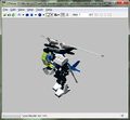
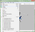
The first thing you want to do is create your LDraw model in MLCad, LDCad, or whatever 3D modeler you prefer. When you are done, load your model in LDView and position your camera where you intend to view the scene from. In my case, I used the default camera orientation. When your camera is positioned properly, go to the "File > Export..." dialog, and export your model to a POV-Ray file. Again, I used the default settings, but you can change them to whatever you want to increase the render quality and so forth.
Note that L3P versions 1.3 and 1.4 both natively support stereoscopic views, so you may be able to skip some of the next few steps if you decide to go that route.
Step 2: Using POV-Ray
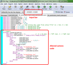
Once you've exported your model in LDView, you should open the file in POV-Ray. If you are using POV-Ray version 3.7 and LDView version 4.1, the first thing you will want to do is insert the following code at the top of the file. Otherwise, the colors will all be messed up. Future versions of LDView may not suffer cause this problem.
#version 3.6
Once you have inserted the above code, scroll down to the section labeled "camera" and replace the camera code block with the following.
// Camera
#ifndef (LDXSkipCamera)
	#declare camera_eye = 1;			// -1 = no eye, 0 = left eye, 1 = right eye
	#declare LDXCamAspect = image_width/image_height;
	camera {
		location	LDXCameraLoc
		sky		LDXCameraSky
		right		LDXCamAspect * < -1,0,0 >
		look_at		LDXCameraLookAt
		angle		57.822403
		translate	-LDXCameraLookAt
		#switch (camera_eye)
			#case (0)
				#include "transforms.inc"
				Axis_Rotate_Trans(+y, +5/2)
			#break
			#case (1)
				#include "transforms.inc"
				Axis_Rotate_Trans(+y, -5/2)
			#break
		#end
		translate	+LDXCameraLookAt
	}
#end
Note the variable named "camera_eye". This variable controls which "eye" is being simulated. 0 means the left eye, 1 means the right eye. For now, leave this variable set to 0.
To get good results, you want to render your image at a very high resolution. Each output image needs to be roughly 3 inches wide and 3 inches tall, and a dpi (dots-per-inch) value of 1200 is a good target when printing on most home inkjet printers. Therefore, you want to render at 3600 x 3600 pixels (1200 dpi multiplied by 3 inches = 3600 dots or pixels).
Since 3600 pixels by 3600 pixels is not one of the default output image resolutions, you will have to either edit the POV-Ray INI file, or type some extra command-line options into the POV-Ray input bar. For the sake of brevity, I will ignore editing the INI file, and instead tell you to type the following into the input bar.
+W3600 +H3600
Again, there are additional command-line options you may want to use to improve the quality of the output image, but I will leave those for you to discover on your own.
You are now ready to render the first image. Click the "Run" button to render the image corresponding to the left eye. This may take several minutes.
When POV-Ray has finished rendering, locate the output image (I recommend the PNG format) in whatever folder you specified as the output directory. (I am not going to explain how to do this.) When you have located the output image, rename the file to "Left".
Now, in POV-Ray, locate the "camera_eye" variable again and this time set it to 1 instead of 0. This means you will now be rendering the image for the right eye. Save and render the document. When POV-Ray is done rendering, locate the new output file and rename it to "Right". You are now ready to process the output images in StereoPhoto Maker.
Step 3: StereoPhoto Maker
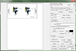
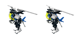
StereoPhoto Maker is a freeware program designed to process left and right eye photographs and images into stereoscopic and anaglyph 3D images. You can download it from the Web. (I can't post a URL here since the wiki software is blocking me.) If you have anaglyph or red-cyan 3D glasses, you will want to create an anaglyph image. If you have a stereoscope, you will want to output a stereoscopic image. I recommend the latter since it will not mess up the image's colors like an anaglyph image will.
Once you have downloaded and installed StereoPhoto Maker, start the program and open the "File" menu and select "Open Left/Right Images...". This will open a file dialog where you can locate the "Left" and "Right" images you rendered in POV-Ray. Once you have located them, select the "Left" image and, while pressing the CTRL key on your keyboard, select the "Right" image. Make sure to select them in that order. The program window should now show both your images, withe the "Left" image on the left side and the "Right" image on the right side.
You now have a couple of choices. You can either, a) assemble the two images into a single stereo image, or b) print a stereo card directly from within StereoPhoto. Both options are accessed from the "File" menu. If you do the former, you can print the image later from your favorite graphics program, such as XnView, or even view it from your smartphone if you own one. The latter is easier, however, so I will describe it instead.
Click on the "File" menu and select the "Print Stereo Card..." option. This brings up a new dialog showing what your images will look like when you print them. Here you can alter the text that appears on the card, as well as the background color and optional rectangle around the image. I suggest leaving the background color white and enabling the rectangle. Also, leave the first setting at the top of the dialog set to "Classic stereo card (7 x 3.5 In)". If you would like, you can select "Add image" and add additional images to your document so you don't waste paper. I'm not 100% clear how this works, so you will have to experiment. When you are ready, press the "Print..." button.
Step 4: Printing
After pressing the "Print..." button in StereoPhoto Maker, a new dialog will pop up allowing you to switch between printers, or configure the printer options. This is a good place to set your printer configuration by pressing the "Preferences" button. I suggest printing on photo paper at the highest quality your printer is capable of. The images are going to be small, so you want them to be as crisp and clear as possible. The images are going to be under magnification when you view them, so every flaw is going to be visible. Leave your printer in its default Portrait orientation. When you're done altering the printer configuration, press "Print". When your document is done printing, cut along the rectangular border surrounding the image. The result should be a card that is 7 inches wide and 3.5 inches tall, with the images themselves being roughly 3 inches by 3 inches, each.
Step 5: Choosing a stereoscope
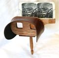
There are a number of different stereoscopes you can order to view classic stereo cards. The most famous is the Holmes stereoscope, which is basically a stick with a handle and a card holder on one end, and a leather shade on the other end. These run between $50 and $100 on Amazon. You can also buy a mirrored stereoscope that works with larger images. These can cost up to $500, so I don't recommend them. Instead, I recommend a very cheap cardboard stereoscope called the "Loreo Lite 3D Viewer". It costs less than $5 on Amazon at the time of this writing, and can be folded and mailed in an envelope. I have a pair of these, and they work quite well. (Again, I can't post a URL because the wiki software is blocking me.)
However, some people don't require a stereoscope and are able to view stereoscopic images using just their eyes. One such method is called the "parallel" viewing method, and involves staring past the image into the distance as the two frames merge into a single image. Another is called the "cross-eyed" method, and involves crossing your eyes until the images merge. It is supposed to be easier on the eyes, but in order to do this, the left and right images need to be switched so that the left image is on the right side, and the right image is on the left side. (This can be done automatically in StereoPhoto Maker.) I was never able to accomplish either method, so I recommend sticking with the cardboard stereoscope.
