LDraw Files Requirements
Parts made for the LDraw parts library are bound to certain technical restrictions. These restrictions may confuse new part authors and thus they are listed here, along with the methods of fixing them. Taking care of these restrictions will also give more probability for fast certification at the parts tracker.
These issues are checked for and typically corrected by the DATHeader tool.
Issue types
Filename and title length
Filenames of parts are to be no longer than twenty-five characters, including the .dat-extension. This restriction was eight characters plus the .dat-extension (DOS filename length), but was recently extended. Titles of parts are to be no longer than sixty-four characters in length.

Complex quadrilaterals
Complexity means that the internal facet lines of quadrilaterals intersect themselves. They are also nicknamed as "bowtie quadrilaterals" on the parts tracker. They are corrected by changing the order of the vertices, making it simple again. Complexity is not an issue for triangles as they, having only three vertices, are unable to intersect themselves.

Concavity
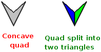
Concavity means that an internal angle of a quadrilateral is greater than 179.9 degrees or smaller than 0.025 degrees, as taken from the official specifications. The fix for concavity is to split them into two triangles. Triangles, having only three vertices, are always convex.
Non-co-planarity
Non-co-planarity means that all vertices of a quadrilateral do not reside in the same plane. Quadrilaterals like this, that have one point outside the plane, are also nicknamed as "warped quads" on the parts tracker. These quadrilaterals are typically present in curved shapes. Non-co-planar quadrilaterals are tolerated up to three degrees, with one degree limit being "ideal", especially for large quadrilaterals. The fix to these quadrilaterals is to split them into two triangles. Triangles, having only three vertices, are always co-planar.
Collinearity

Collinearity means that three or more vertices of a polygon reside in the same straight line. Polygons like this are also nicknamed as "degenerated or deformed polygons" on the parts tracker.
These are dealt with case-by-case basis. Collinear triangles, being only lines, are typically deleted, while quadrilaterals are either turned into triangles by deleting the middle vertex within the line (if three within same line) or deleting it entirely (if all four). However, needle polygons like this can be troublesome as their lengthy facet lines might warp a little bit after reforming, causing gaps, so care should be taken when correcting these.
Duplicates
Two or more copies of the same, identical polygon or subfile may not exist within the file. They are typically easy to fix by just deleting the duplicate in question.
Overlapping and intersecting
The exact rules for overlapping may be confusing. According to the official specifications:
All or part of a line (line type 2) may not overlap all or part of any other line (line type 2).

All or part of a conditional line (line type 5) may not overlap all or part of any other conditional line (line type 5).

Part (but not all) of a conditional line (line type 5) may overlap all (but not part) of a line (line type 2).
Consider the line A-B-C-D
If AB and CD need to be conditional lines and BC a line, it is acceptable to define this as a line BC and a single
conditional line AD
If AC needs to be a line and just CD needs to be a conditional line, it is not acceptable to define the conditional
line as either AD or BD
If AD is a line, there are no valid conditional lines along the length of AD

Lines (line type 2 or 5) may intersect any other line (line type 2 or 5).

Every effort must be made to remove overlapping co-planar polygons (line type 3 or 4). Where overlapping polygons are
unavoidable, the overlap must be kept to the absolute minimum.

Every effort must be made to remove intersecting (non co-planar) polygons (line type 3 or 4). Where intersecting
polygons are unavoidable, the intersection(s) must be kept to the absolute minimum.

Note: Primitives that overlap/intersect other primitives or polygons (line type 3 or 4), provided that the overlap
is small, are considered acceptable. The intention is not to force part authors to in-line primitives. However, there
may be some cases where it is better to use (say) a 3-8cyli and a quad than a 1-2cyli; case-by-case decisions are left
to the parts review process.
However, these rules are often flouted in the interests of saving disk space and for convenience of the part authors. Polygons and primitives typically bleed into the interiors of parts as the interiors are not seen by the end user. However, polygons of different colours may not overlap each other and every effort should be taken to remove overlaps and bleed-ins when the part in question is sold by LEGO in transparent colours.
Matrix rule
Matrices of subpart references may not contain rows or columns all zero. Say, an edge circle of:
1 16 0 0 0 1 0 0 0 1 0 0 0 1
is considered valid, but:
1 16 0 0 0 1 0 0 0 0 0 0 0 1
has the Y-row (middle row) all zero. Also, seen the other way, the second line has the middle column all zero (all middle numbers are zero).
Colour restrictions
Polygons may not use the edge colour #24, nor can lines use main colour #16. In the past lines using main colour were used for:
- where a line is being used for fine detail within a pattern and that pattern is re-used within many parts (and hence sub-parted) in different colours (for example, sub-part s/973p11a.dat)
- when a sub-part pattern leaves a narrow gap of base-part colour around the pattern (for example, see sub-part s/973p11b.dat)
(as taken from official specs). However, gaps are these days not really tolerated and fine details is no longer marked with lines.
All colours, except for pattern colours, must be present within LDConfig.ldr
Also polygons should always be of colour 16 unless a printed pattern is in question. This is not mentioned in official specifications but is enforced on the parts tracker.
Header specifications
The header is these days formalized and should be formatted in new parts. While not typically enforced by hold votes on the parts tracker, it is polite, and a good practice, to format the header when submitting parts to cut down the work the tracker administrator needs to do. The DATHeader tool was made for automatic header formatting in the first place and does this job well.
Line termination
All lines are to be terminated with a <CR><LF>-sequence, i.e. the DOS line ending. The last two bytes of part files are to be the DOS line ending as well.