Conversion 101
Warning! This article is a legacy article from the old site. It is provided for historical context and information may no longer be relavent.
By: Jeroen de Haan and Jake McKee
Posted: May 11, 2002
Version: v1 rev.1 110202
Knowledge Requirements
What your reading now is a beginners guide to L3P/L3PAO and POV-Ray. It assumes you have some knowledge of and experience with LDraw and one or more of its editors (such as MLCAD, LeoCAD, BrickDraw3D, etc) and creating models. What it wants to provide is a step by step guide of converting LDraw-models to POV-files and rendering them and what options you have when converting or rendering. What you won't find here is how to create models or parts.
Some chapters are on the practical side; you will do things after reading it. Other chapters are more theoretical, for example about cameras and lenses or color and light. Please read these chapters too. We try to make them as short and "light" as possible but they are important to understand some of the functions and options of L3P and POV-Ray.
Chapter 1: Introduction
So you have made some models; your own or existing Lego models. Now you want to have a nice picture of it, like the ones you see on Brickshelf or on other people's websites. However, your editor for LDraw can't so how do people do that? What you need is three programs and some additional files:
- L3P: a program that converts .DAT, .LDR and .MPD files to .POV (the native file format for POV-Ray)
- L3P AddOn (or L3PAO for short): a graphic interface for L3P
- POV-Ray: a freeware program to ray trace POV-files
- The LGEO-files for POV-Ray.
L3P is a DOS-program. It uses switches to call certain options. So for example, when you want your model with a certain camera position and background color you have to type the following in the DOS-prompt: L3P.exe tp-7745.dat tp-7745.pov -cc0,-96,-250 -ca45 -b0.000,0.000,0.251 -o You have to know (all) the options and their acronyms and when you make a typo, (and who doesn't now and then) you have to type it all over again. Or if you want a batch of models you have to retype the whole line over and over again.
This is why J. Boen created L3P AddOn, a graphic interface for L3P where you can turn on or off options in an easy way AND can save these options in "scenes" or snapshots.
POV-Ray is a freeware program to create and render computer generated pictures or animations. POV-Ray has no graphical interface in the sense that you see what you create; it has a source window where you type text commands and you can see what you created when you render the picture. Luckily, you don't have to learn all these commands; L3P creates a ready to render POV-file!
The LGEO-files for POV-Ray are files that POV-Ray uses to substitute some of the LDraw parts. The LGEO-files look better; cylinders are rounder, sloped bricks have that sandpaper structure, etc. They are also harder to render for POV-Ray; you will need lots of memory to use them.
However, before you can make a nice rendering of your model you have to download the above mentioned software. We going to guide you with installing the programs but please read the installation guides of each program carefully!
Chapter 2: Downloading and installing L3P, L3PAO and POV-Ray and LGEO
L3P
L3P is no longer distributed as part of the LDraw All-In-One-Installer, and you will need to obtain it directly from the author's web site: http://www.hassings.dk/l3/l3p.html. The download links are near the bottom of the page.
- After downloading l3p14beta.zip place the ZIP-file in the LDRAW-directory and unzip it. There are now two files in the LDRAW\L3P directory: L3P.EXE and L3P.TXT.
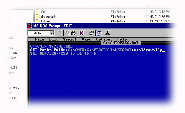
- DOS has to know where it can find L3P. Open a simple text editor like Notepad and open the AUTOEXEC.BAT or type "EDIT C:\AUTOEXEC.BAT" in the DOS-prompt.
- There probably will be a line starting with "set PATH=%PATH...". Place your cursor at the end of that. Now type the following sentence: ;C:\LDRAW\L3P (see below) and hit "Return" or "Enter".
6. Now L3P has to know where it can find the LDraw parts and models. On the new line type:
SET LDRAWDIR=C:\LDRAW (see below) 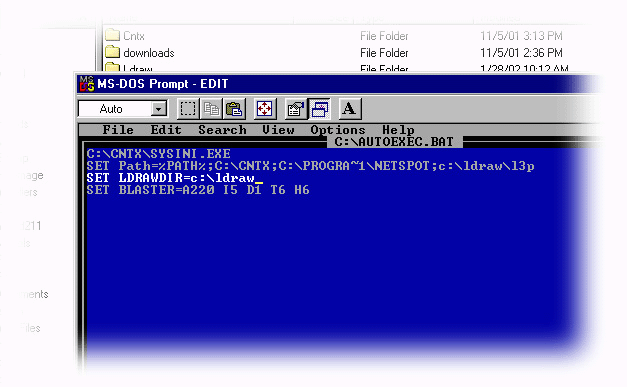
assuming the LDraw-directory is there. If you have placed it somewhere else please type the correct directory tree after C:\
7. L3P also needs to know where the LGEO-files are so in a new line under the SET LDRAWDIR line type:
SET LGEODIR=c:\ldraw\lgeo
Now every time you start up, DOS will read these commands and "know" where L3P is and where to find the LDraw parts and LGEO-files.
8. So, before going further with the L3PAO installation, please restart Windows.
L3PAO
Like L3P, L3PAO is also no longer distributed as part of the LDraw All-In-One-Installer, and you will need to obtain it directly from the author's web site: http://l3pao.malagraphixia.com.
- L3PAO.ZIP contains three files that should be unzipped in a temporally directory.
- Double click the SETUP.EXE and follow the instructions on screen. It is very simple. All you have to do is to point to the directory where L3PAO should be. By default, this is Program Files\L3PAO but the L3PAO manual recommends the same directory as where L3P is placed. So, hit the change directory-button and change the directory to c:\LDRAW\L3P.
- Now click the button with the computer icon on it. L3PAO will be installed. When finished it is ready to use, no restart needed.
- When you open L3PAO for the first time, it wants to know were it can find L3P (choose the LDRAW/L3P directory), Ledit (in the LDRAW directory) and LGEO-parts. Please point to the right directory.
- If you haven't installed POV-Ray and you open L3PAO, you will get a warning about that. Ignore it, close L3PAO and read on...
LGEO and POV-Ray
Both of these tools are part of the standard LDraw package. If you do not already have them installed, go to the "Get Started" page at http://www.ldraw.org/help/getting-started.html, choose the appropriate platform, then follow the links and instructions.
You are ready to go now!
Tips
- Keep an eye on the various lugnet newsgroups for software updates: lugnet.cad.ray (for POV-Ray), lugnet.cad (for the others) or check ldraw.org.
- Lugnet.cad is also the place to post questions. However, before posting a question do a search to find out if no one posted the same question before you.
Chapter 3: First conversion and rendering
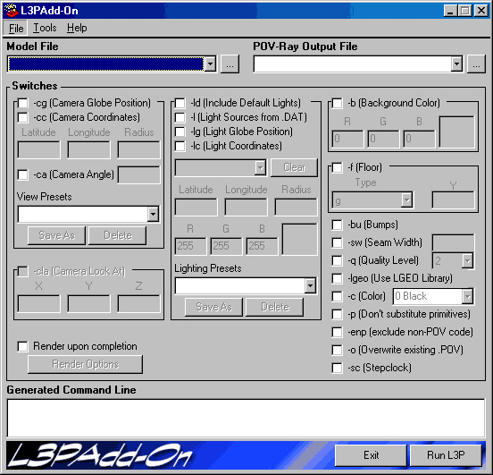
All the software is installed and you are ready to go! From the Start menu, choose L3P Add-On. The program starts and will show the following window:
The L3PAO Interface
Across the top you see three menu-items: File, Tools and Help. Below this are two text fields: the Model File (input) and POV-Ray Output File (output). Then there is the "switchboard" which is divided in 3 columns: camera, lights and other commands. Below these three columns is the "Generated Command Line"-box. This is where you can see (but not edit) the command line, which will be sent to L3P when you hit the "Run L3P" button bottom right. And lastly, the "Exit" button next to the "Run L3P" button, which will simply close the application.
The commands in the three "switchboard" columns will be covered in detail throughout this tutorial. Some of the more advanced topics are not covered. They will be discussed in other tutorials.
Alright, let's get started!
First, we need to load a .dat or .ldr model. To do this, use the "Model File" pull-down menu. Find a model file on your computer, by hitting the "..."-button to the right of the pop-up. You will be presented with a standard Open window where you can browse your computer. Throughout this tutorial, we will use the CAR.DAT, which is located in the LDRAW\MODELS-directory on your computer. This file is copied on your hard disk by the LDraw installer.
Because it is the first time you use L3PAO click the "..." button next to the "Model File"-pop-up. Browse to the LDRAW\MODELS-directory, click the CAR.DAT file and click "Open". The POV-file will be generated in the same directory as the DAT-file, unless you choose to specify a different location. For this example, we will not.
Uncheck "render upon complete" located near the bottom of L3PAO. Now click the "Run L3P" button. A DOS command window will appear and you will be able to watch the L3P commands run. However, if you have a fast computer, the box will disappear before you noticed it was there!
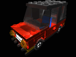
So now it is time to make your first rendering! Open the LDRAW\MODELS folder from your desktop and double click the CAR.POV file. The POV-Ray program will open, and will display the POV-Ray source code.
Before we get into any detail about POV-Ray, follow these instructions:
- On the top left-hand side, there is a pull-down menu with a series of dimensions. Choose 320 x 240, NO AA
- Hit the Start/Run button at the top of the interface to kick off your very first rendering
- POV-Ray will double check the code and prepare to render the car.pov file.
- After a few seconds (depending on your computer speed and the size of the file) a new window will open and line for line your first ray-traced (rendered) LEGO image appears!
Chapter 4: A better first rendering
Yikes! It isn't what you hoped it would be, is it? It is a bit dark ...sort of a "car floating in space. Well you are right... the car is floating in space!
When making LDraw models, you usually don't need to define floors or backgrounds. Ldraw models look fine floating in space because of the flat, 2-Dimensional nature of the look. However, when you create a fully ray-traced model, you see something much closer to items in the real world that you see every day. When you see this "real" image, you expect it to also appear as though it is in a real environment. So let's fix this!
Open L3PAO again and choose the CAR.DAT again. If you look in the right side column, you will see two options: background (-b) and floor (-f)
Click the checkbox to select background. The default background color in L3PAO is black,however, for our new rendering we will choose a different color. Click on the big black square, and a color picker window will open. Choose a nice shade of blue from the predefined colors. Click "OK".
Now select the floor option. By default, the floor is a light shade of gray, but we have some options to change that. There is a pull-down menu were you can choose between "g" (gray) or "c" (checkered, like a chess board).
In addition, there is a box with "Y" above it. This is the distance between the model and the floor. By default, this number is zero and this means the lowest part of your model will touch the floor. You can adjust this distance to make different effects. For instance, if you wanted to render an airplane or other flying object, you can lower the floor to make the model appear to be flying.
For our rendering select the "g" (gray) floor option, and leave the Y field blank. This will provide a rendering of the car sitting on a gray floor.Now, let's see what these new changes do for the rendering. Before we convert the file with these new options, let's change the "output name" of the file, to avoid overwriting our original car.pov file. In the "POV-Ray Output File" field at the top of the interface, change the name CAR.POV to CAR01.POV.
Now we are all set, so hit "Run L3P", and when it is done converting, switch back to POV-Ray, load the new CAR01.POV file, and Hit the "Start/Run" button to render.
Note if you check off "Render upon complete" in L3PAO. L3PAO will open POV-Ray for you automatically and render the image using the last setting that POV-Ray had.
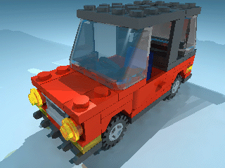
The result should look something like this:
Ah, that looks much better!
Because we have added the added floor, much more light will reflect back on the car, so the car looks much better. In addition, the car casts shadows on the floor so you get a lifelike image. The background will reflect light in the same manner as the floor, but since the background color is blue, the light being reflected is also somewhat blue. You can always change this by changing the background color to white.
Next stop: camera and lenses!
Chapter 5: Camera and lenses (part 1)
For a picture, you need three things: a model, light and a camera. Leave one out and the will be no picture (a Zen Buddhist would say you also need someone to watch the picture but more on that in the tutorial "Zen and the Art of LDraw).
With what we have rendered so far, you don't need to think about lights and camera placement. L3P very kindly places both of them for you at "fixed" locations. However, many times, you will want to change them to better suit your needs. So let's dive into camera placement and how L3P knows where to place it!
Before we start actually talking about the camera, we need to make sure that we understand the world the camera lives in, so to speak.
L3P uses the same coordinate system as LDraw. Remember those X, Y, Z axes from math class? Well, they're back! The X axis can be though of as the left to right plane, Y is the up to down plane, and Z is the forward to back plane. X and Z are parallel to the floor, while Y is perpendicular.
All three axes have both a positive and negative direction. Each axes changes from positive to negative at the center point of the globe. LDraw's coordinate system defines the axes in the following way:
+X (or simply X): Moving along the X axis to the right
-X: Moving along the X axis to the left
+ Y: Moving along the Y axis upwards
-Y: Moving along the Y axis downwards
+Z: Moving along the Z axis into the background
-Z: Moving along the Z axis into the foreground
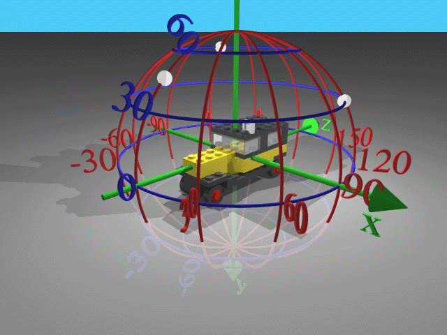
If you take a look at the picture below, you will see all three axes, as well as a "globe" that is formed around them. This globe is the key to understanding how to move the camera and lights. L3P considers the model to be placed inside this globe, with the center point of the model's bounding box at the same place as the center point of the globe. (For reference, the Bounding Box is an imaginary box that the model fits in exactly. The top of the box lays on top of the highest point of the model, the bottom at the lowest point, and so on.)
Based on this globe system, the camera and lights can be easily placed by specifying Latitude, Longitude, and Radius (also known as polar coordinates).
Latitude is in the range from -90 degrees (south, along the positive y-axis) to 90 degrees (north, along the negative y-axis). Zero degrees is at the equator. Longitude is in the range from -180 to 180, where 0 degrees is along the negative z-axis. 90 degrees (east) is then along the positive x-axis and -90 degrees (west) is along the negative x-axis.
The basic LDraw views can be represented by these Latitude, Longitude pairs: Front=0,0 Right=0,-90 Left=0,90 Back=0,180 Over=90,0 Under=-90,0.
By now, you are probably asking, "This is great and all, but how do I move the camera around?" So let's dive into it!
The camera is placed at a certain distance from the model, which is called the "radius". By default, L3P calculates the radius so that the model fits very tightly in the rendering window. If you look at your last rendering, you see that the roof of the car is almost at the edge of the rendering window as is the bumper. If you want to specify a different camera globe position, L3P wants to know three things: the latitude (north or south position), longitude (east or west position) and radius (camera distance). As you can see in your last rendering, L3P calculates the radius so, that the model fits almost exactly in the picture. If you want you can move the camera away from the model so there is more space around the picture. The amount you give is a percentage.
By default L3P will place the camera as close as possible to the model. The viewing direction will be parallel to the direction given by the latitude (<la>) and longitude (<lo>). This won't necessarily be through the globe's center (also the model's center).
Think of the camera view towards the model as a funnel, with the point of funnel at the camera lens and the open end pointing towards the model. The funnel will be rotated so that its centerline is parallel to the direction vector defined by <la> and <lo> coordinates. L3P will move the funnel towards the model until it cannot come any closer.
The rendered image may look a bit distorted when the camera is moved that close, but this is to minimize the waste of empty rendered area. However, to get a nicer looking image (and a better look at the shadows) it may actually be better to have some amount of space around the model. To add this space, simply move the camera away from the model along the direction vector. If you specify a negative radius, e.g. -20, the camera will be moved 20% further away.
Yeah, yeah, you just want to do more rendering right? So let's do!
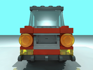
Open L3PAO, select CAR.DAT again and change the output name from to CAR02.POV Now go to the left column in the "switchboard" and check the -cg box. In the three input boxes, type in 0, 0, and -10 from left to right. Don't forget to add a floor and a background!
Hit "Run L3P", and then render the new CAR02.POV file
It will look like this:
Do you see what you did? You positioned the camera at the front of the model, and moved the camera back 10%. Fun, eh?
Now experiment for yourself on views. Try some different latitude and longitude settings to get a good feel of the polar coordinate system.
As an added feature of L3PAO, there is a "View Preset" pull-down menu that offers several standard views. These presets are already set to use the correct latitude, longitude, and radius to render some standard angles. You can use these as-is, or choose a preset and change the parameters a bit.
Chapter 6: Camera and lenses (part 2)
The radius (distance) of the camera from the model is calculated by L3P automatically for you. The camera radius depends on two things: the size of the model and the camera angle (or actually camera lens angle).
Camera angle, you ask? The lens of a camera has a certain angle, which determine what is visible and what is not. Basically how far to either side the camera can see. Human eyes have a viewing angle of 45 degrees, while the default camera angle in L3P is 67 degrees. Look at the picture below.
Lenses have their own characteristics:
The normal lens (45°) will give a normal view.
The telelens (<45°) will even the perspective: when using an extreme telelens you won't have perspective at all and all objects will have the same size; objects in the front and in the back of the picture.
The wide lens (>45°) will distort the perspective: objects in the front look extremely big while objects in the back are very small, even in short distances.
Let's say the camera in the pictures above has a fixed distance towards a, b and c. The first camera has a standard lens. Not all the objects are visible (from this distance).
The second lens is a tele-lens; only a small part of the picture is visible. Sports and wildlife photographers use this kind of lenses because you can get very "close" to an object from a distance (zoom in).
The last lens is a wide- or fisheye lens; all the objects are visible. This is used in landscape and interior photography because you can get a lot on a picture without taking too much distance.
L3P uses the size of the model and the camera angle to calculate the radius. Lets say the two outer c's are the outer most part of a model. If you want to use a 45 degrees lens (as in the first camera), you have to move from the object. When using a 15 degrees lens you also have to move but a bit more extreme. In the last picture, you have to move to the model a bit.
Confused? Well let's try how it looks.
Open the CAR.DAT in L3PAO, add a floor and background and make 3 POV-files using Camera Globe Positions:
30,45,0 and Camera Angle 10 for CARCA010.POV
30,45,0 and Camera Angle 45 for CARCA045.POV
30,45,0 and Camera Angle 100 for CARCA100.POV
Open POV-Ray and render the pictures one by one.
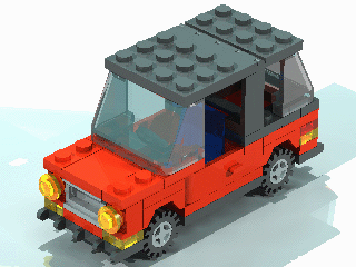
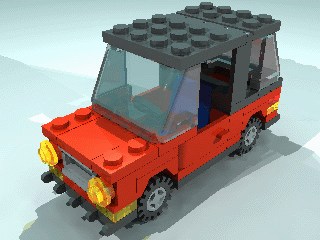
The three pictures look like this:
This is the image rendered at a 10 degrees camera angle. You notice that the perspective lines are almost parallel. This is great when you want to render building steps of a model. The camera radius is roughly 1453 LDraw units (a 1 x 1 Brick is 24 LDraw units high).
This is the image rendered at 45 degrees camera angle. It has a much more life-like perspective. The camera radius is now just 334 LDraw units.
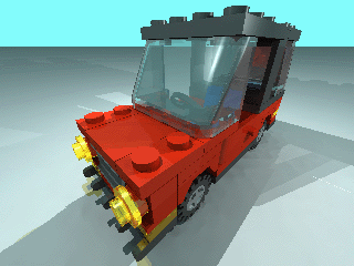
And last: the image rendered at a 100 degrees camera angle. You will notice that the picture is quite different: you can see the horizon now because the camera is closer and lower to the floor, which causes the car to look a bit odd. You can see how distorted the perspective is: the two red studs on right side of the bonnet are almost twice as large as the two studs on the left side. The camera is now only 194 LDraw units away.
If you look at the shadows on the floor, you will notice that these are different too. This is because, by default, L3P places 3 lights on fixed globe locations and at the same radius as the camera. Therefore, in the CARca045 image the lights are very far away and lit a large part of the floor while in the CARca100 image the camera, thus the lights are very close to the model, and a much smaller part of the floor is lit. Hence, the floor looks darker on the horizon.
Chapter 7: Taking the camera out of the globe
The default Camera Globe position is nice for pictures of the outside of a model. But what if you want a picture from within a model, almost as though you were inside the model looking out? You could change the radius to very small negative number so the camera will be in the model but the outcome will be very unpredictable. Therefore, it is better to take the camera from the globe so to speak and give it a fixed location. Instead of using the Camera Globe Position, we are going to use the Camera Coordinates in this chapter.
To get started, we need two coordinates: the camera coordinate and a "look at" point: the point where the camera will look at (or point at). These coordinates are LDraw coordinates so it is easy to determinate these.
Open the CAR.DAT in your LDraw editor (because I use and know MLCad best I will use that in this example but any other editor will do).
Place a 1 x 1 Brick inside the car above the chair at a height of a minifig's head. Make a note of the coordinates, which we will call -cc (it will be something like 0, -72, 10). Now place a 1 x 1 Brick in front of the car approximately at the same height as the one inside the car. You can place it a bit lower than the one inside, but don't over do it. Make a note of the coordinates, which we will call -cla (it will be something like 0, -56, -310). Delete both 1 x 1 Bricks and close the editor, without saving CAR.DAT.
Open L3PAO and open the CAR.DAT. Add a floor and background. Select the Camera Coordinates box (-cc), and fill in the coordinates in the three fields. Now select the Camera Look At box (-cla) and fill in the coordinates in the three fields. Change the output name to CARCC.DAT. Click "Run L3P" and open the .POV file.
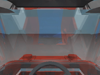
After rendering, it will look like this.
Now you know what a mini-fig would see when driving a car! You can see the steering wheel and the reflection of the drivers seat in the window. You will have noticed that the time it took to render was considerable longer than the other pictures. This is because POV-Ray had to render through the windscreen and has to calculate all the refractions and reflections.
Now let's do this again, but from the outside to the inside of the car, like a car promotion brochure.
Open the CAR.DAT again in an LDraw editor. Select the steering wheel and make a note of its coordinates (0, -16, -30) , which will be the Look At coordinates (-cla).
Place a 1 x 1 Brick outside the car at the height of the roof and by the door. Make a note its coordinates (80, -80, 20), which will be the Camera Coordinates (-cc).
Now close the editor (again, don't save) and open L3PAO. Open the car, fill in the coordinates in the right fields. Choose 45 as camera angle (-ca). Select a floor and a blue background. Change the output file to CARCC2.POV.
Before you run L3P, we are going to save all these options in a "Scene".
Open the File menu and click "Save Scene". A standard Save as... window opens with L3P as directory (don't change that!). Now save the scene as CARCC2.xxx. If you were to close L3P (don't, but let's say) and want to use the same settings/options, all you have to do is open a DAT/LDR file, select "Open Scene" from the File menu and you are ready to go! No need to write everything down!
Hit "Run L3P", exit L3PAO and open CARCC2.POV in POV-Ray. Hit the "Run" button and wait...
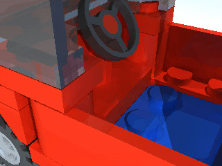
The above image is the result. Because the rotation point of the Steering Wheel is at the bottom of the part, we are looking at the bottom of the car, or in other words: the center of the picture is not the steering wheel.
The good news is, is that we saved the options (phew!) and don't have to open the car in an editor to determine the coordinates.
Open L3PAO, load CAR.DAT and choose "Open Scene" from the File menu. Open the CARCC2.xxx. You see that all the parameters you used last time are back! Now all you have to do is to change the Y coordinate of the Look At point. Let's try two plate heights (or 32 LDraw units). So change the -16 in the second Look At box to -32.
Change the output name to CARCC3.POV, hit "Run L3P", exit L3PAO and open CARCC3.POV in POV-Ray. Hit the "Run" button and wait again while the image renders.
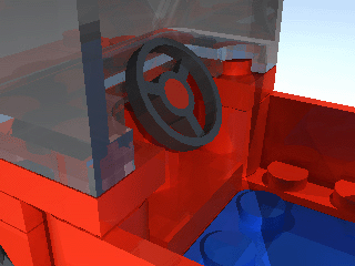
Yes, that is much better! The steering wheel is more in the center of the picture now.
Tips
- Start working out the Camera Globe position. Use the "car in the globe" picture to determine the position of the camera. Start with simple models first.
- Use the camera angle creatively but with care: use normal or tele-lenses (<50 degrees) for model presentation. Use a wider lens (>60 degrees) to add dynamics to a model or scene or to make it more "dramatic".
- Creation should be 90% Inspiration and 10% Transpiration. Look at real life pictures of objects similar to your model: how did other photographers take their picture? What was their point of view: low (or frog-view), normal viewing height or from a higher point (birds eye). Or think mini-fig height. Use a mini-fig to determine the camera coordinates.
